A Warehouse Notification System
When I worked at Staples, the general manager at the time expressed a need for a way to know when someone walked through the warehouse doors, as we had had issues with customers walking in without our knowledge. I asked if I could design and build something to ammend this issue, and with authorization I went forth and began deliberating possible ways to accomplish this.
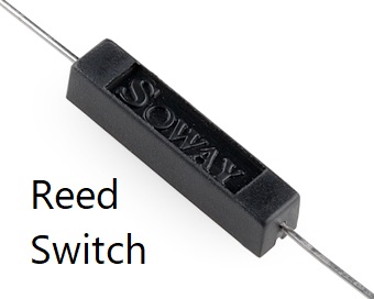
Eventually I settled on using reed switches. These are little devices that are designed to close when a magnetic field passes over it. The warehouse entrance is comprised of two large double swinging doors with a metal frame around the whole doorway. The reed switches were placed along the top edge of the door with the wires leading to the device. The steel frame is of course ferromagnetic, so small flat neodymium magnets were stuck right above where the path of the reed switch passed over when the door was opened. Thus, when the door was pushed, the reed switch would pass over the magnet and close momentarily, telling the device when the door was opened.
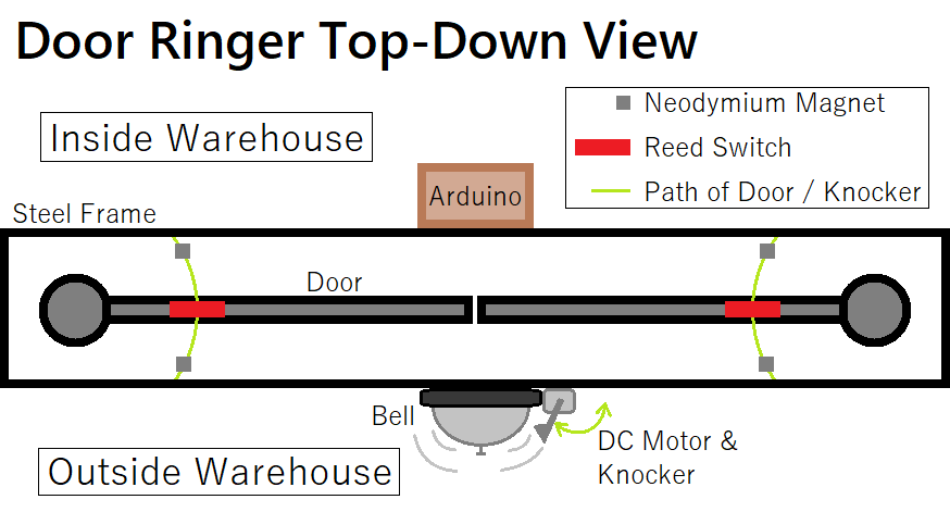
A desk bell was used for the notification tone over a buzzer since the sound is much less jarring. The knocker inside the bell was removed and attached to the axis of a small DC motor, which was then fastened to the side of the bell. This way, when the device sent a signal, the motor would quickly spin, knocking the bell and producing a sound.

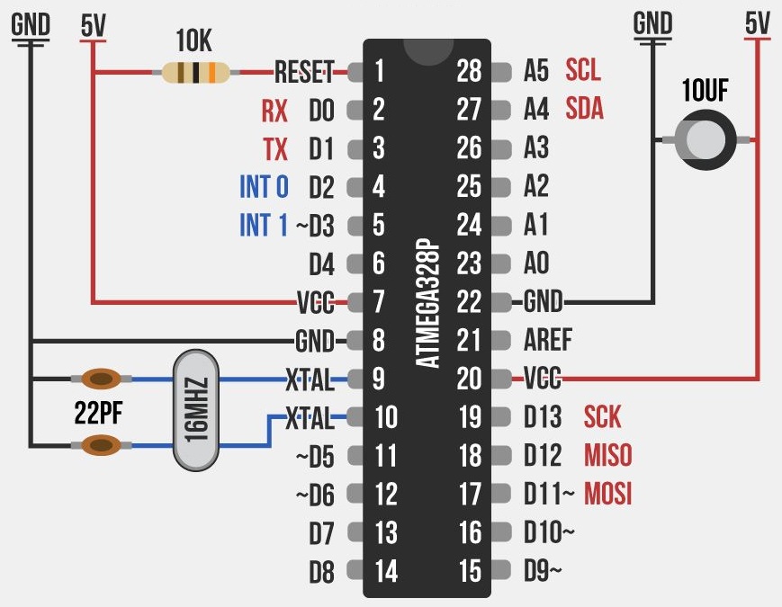
For the device itself, it was comprised of a custom made Arduino. A blank ATmega328P was flashed with the proper bootloader, and then flashed with the written code. A socket (for the IC to be placed in) was then soldered to blank copper-dot perfboard with the 16 MHz clock, 10 kΩ resistor, and required capacitors. A mosfet to acitvate and deliver power to the DC motor directly from the supply was also added. An on/off switch and connective ports for power and I/O were glued into the frame of a small wooden box. They were then connected to the main board which was finally sealed inside the case before being mounted above the doorframe inside the warehouse.
Once deciding on an approach, I made a complete inventory of all parts that needed to be purchased, a timeline and estimated time to completion, drafted into a contract and invoice. Once signed off and payment had been received, the parts were purchased and the device was built ahead of schedule, before being installed on site.
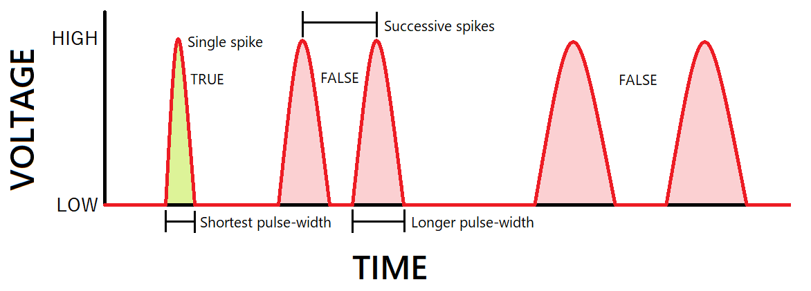
The reason the arduino was required was due to the fact that these doors swing back and forth, multiple times. If the motor was connected directly to allow power to pass through the reed switches on activation, it not only wouldn't have enough time to fully swing the knocker, but it would also repeatedly activate twice every time the door swung back, making it not only quite bothersome, but also wearing out the motor much more rapidly. Instead, an arduino was programmed with an algorithm to detect and negate false inputs.
When the arduino receives a signal from the reed switches, it activates the mosfet which drives the motor to quickly ring the bell before gravity brings it back to its original position. It then waits a few hundred milliseconds and ignores any false swings it detects. Usually the first activation has the shortest spike since it has the most momentum, which allows you to compare whether the next spike was as short as the first, and if not, ignore it as false. It also detects whether there are two successive spikes close to eachother, if so, ignore it as false.
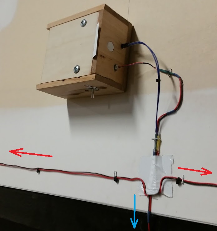
The following is the device after installation, the red arrows are the inputs from the reed switches, the blue arrow is the output to the bell motor on the other side of the wall. The DC power was not connected at the time of the photo, but would connect through the jack on the left side of the box.
